

How To Install Electric Water Pump
Best Sellers
How to Install Davies Craig Electric Water Pump - 150 LPH on your Mustang
Installation Fourth dimension
2 hours
Shop Parts in this Guide
- Electric H2o Pump; 150 LPH (xi-17 Mustang GT)
PLEASE READ THESE INSTRUCTIONS IN THEIR ENTIRETY BEFORE You START WORK
THE EWP IS A 'Circulation' PUMP IDEAL FOR 'CLOSED Excursion' OPERATION SUCH Every bit AN AUTOMOTIVE COOLING Organization.
DAVIES, CRAIG EWP® (ELECTRIC WATER PUMP) AND OPTIONS FOR PUMP Command
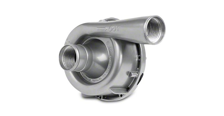
Congratulations on your purchase of the Davies, Craig blend EWP®150 Electric Water Pump. This loftier capacity EWP®150 (twoscore Us Gal/Min) is designed to supercede and/or complement the existing belt driven mechanical water pump. The major benefits an EWP®150 offers are, removal of the parasitic power losses running a mechanical water pump at high speed when not needed, maximise engine warm-up and removal of the effects of heat soak later hot-engine shut down by operating the EWP®150 with the EWP® & Fan Digital Controller (#8020) or one of the Davies Craig Thermatic Switches. Your new EWP®150 has the advantage of offering more consequent coolant period independent of the engine speed.
EWP® COMPONENTS:
| No. | Description | Qty. |
|---|---|---|
| 1 | EWP alloy Pump Assy | ane |
| two | Wiring harness with 10Afuse | i |
| iii | Rubber Sleeves | 2 |
| 4 | Hose Clamps | 2 |
HARDWARE COMPONENTS:
| No. | Clarification | Qty. |
|---|---|---|
| ane | Hardware bag | 1 |
| two | Relay | 1 |
| 3 | Scotch lock | one |
| 4 | Ring Final | ane |
| 5 | Self Tapper | 1 |
SECTION ONE: INSTALLING THE EWP® 150
1. Your EWP®150 Electric H2o Pump is all-time fitted in the lower radiator hose which connects the radiator to the existing mechanical water pump housing. In conventional vehicle operating conditions, the hose will bear the weight of your EWP® 150 and insulates the EWP® from engine vibration. Cheque the area for bachelor space. Farther radiator hose or adaptors may be required. Position the EWP® in the lower hose so the inlet, in the heart of the pump is connected to the radiator side and the outlet (marked with an arrow) is connected to the engine's mechanical water pump housing or EWP Header-Adaptor. The EWP® should be positioned as depression as possible to maximise the gravity feed from the radiator and to avert air entering and remaining in the pump. Alternatively, the EWP® may be fitted in the upper radiator hose. Coolant level is disquisitional and bleeding of all air from the cooling system essential. Follow instructions higher up for correct EWP® fitment ensuring the pump outlet is continued to the hose going into the top of the radiator. The pump can be installed in whatsoever orientation but to assist air bleeding try to mount the outlet pointing upwards.
2. Use Rubber Sleeve Adaptors 2 x 3mm (function #8510) supplied in kit for fitment to the EWP® inlet and outlet, to arrange your particular hose diameter. If you require thicker Rubber Sleeve Adaptors to accommodate 2" (office #8511, 6mm) internal diameter hose contact Davies, Craig Pty Ltd. These tin be shipped to you lot promptly, free of charge.
3. Cut out the not required section of the radiator hose. Connect the pump inlet and outlet to the appropriate hose ensuring hose clamps are very firmly tightened.
Assembly of flanged adaptors ( Optional )
Your Davies Craig EWP®150 Alloy Electric H2o Pump offers you the alternative selection to use the AN-16 internal threads in both the inlet and outlet to attach the appropriate adaptors (equally shown) or screw-in radiator hoses to accommodate your individual requirements.
A pick of Davies, Craig adaptors can be ordered separately. Please consult our website www.daviescraig.com.au or your authorised Davies Craig stockist.
SECTION TWO: OPTIONS FOR PUMP CONTROL
1. With EWP® Fan Digital Controller, P/No - 8020:
We highly recommend the use of the EWP/Fan Digital Controller for maximum cooling efficiency. The EWP/Fan Controller will vary the EWP speed in response to the coolant temperature. You ready the temperature desired for maximum power or fuel efficiency. The Digital Controller has an in congenital part that allows the EWP to run on after hot engine shutdown to eliminate heat soak. Nosotros further recommend the removal of the engine's thermostat and disabling of mechanical water pump. The pump belt can either be removed or left as an idler pulley. The vehicles heater may take a little longer to warm upwards and to meliorate the heating; we recommend the fitment of an Electric Booster Pump (EBP) Part No.9002 to the heater line
2. With Davies, Craig Thermatic Switches, Part #0401 or Part #0402
Combine the EWP® with either of the canonical Davies, Craig thermal switches listed here when the EWP is used every bit a booster pump to assistance the existing mechanical water pump absurd an overheating engine. Connect the thermal switch directly to the battery and your EWP will run on to eliminate heat soak. Y'all may get out the thermostat in place , but ensure the EWP operates but when the thermostat is open.
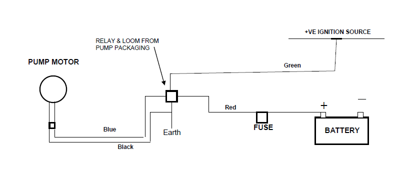
3. Continuous running:
Wire the EWP® direct to the ignition for maximum cooling (race vehicles, very hot climates). This pick requires the removal of the Engine thermostat and the mechanical pump impeller or pump belt. This option may also be used for route cars with the thermostat in identify with a small-scale hole (propose 5mm), allowing a small corporeality of flow to broadcast fifty-fifty when the thermostat is closed.
Alarm: When using the Electric H2o Pump (EWP) on vehicles using LPG, information technology is recommended that an Electric Booster Pump (EBP - Davies, Craig office no 9001)) be fitted to the heater circuit to increase the flow through the heater line and therefore eliminate the risk of freezing LPG in the converter.
MODIFYING EXISTING MECHANICAL WATER PUMP
Either:
1. Remove the existing belt-driven water pump housing.
two. Remove the water pump impeller from the pump shaft. (NOTE: You may need to drill holes through the impeller close to the drive shaft to make it easier to eliminate aforementioned). Alternatively, remove vanes from impeller. Mechanical water pumps differ from engine to engine and you need to take appropriate action that suits the specific h2o pump to eliminate the impellor.
three. Re-fit the water pump housing without the impeller ensuring that there is no damage to the h2o pump gasket and the pump seal is notwithstanding retained. Re-fit the water pump belt and tighten to manufacturer's specifications.
Or:
1. You may choose to past-pass the belt-driven h2o pump pulley by installing a shorter chugalug. This selection may not be possible if the crank pulley drives a belt-driven ability steering and fan or unless yous replace the mechanical fan with a Davies, Craig Thermatic Fan®. For example run into Fig two below:
ii. Remove the thermostat from the thermostat housing.
3. Re-fit the thermostat housing ensuring that there is no damage to the thermostat-housing gasket.
Selection 1: INSTALLING EWP® & FAN DIGITAL CONTROLLER - Part # 8020
Note: Wiring from EWP kit volition not be required withal retain for difficult wiring the EWP during bleeding.
i. The Digital Controller must exist fitted inside the passenger compartment.
2. Connect the wiring harness to the Digital Controller and mount the Controller (using 2 of the screws provided) in an appropriate position --- avoid mounting the controller where it may be exposed to direct sunlight.
3. An additional spiral is provided for mounting Digital Controller fuse holder where necessary.
4. Mount 'Remote Test Low-cal' in a location, which will be visible. The 'Examination Light' may be fitted by inserting it through a iv.6mm drilled hole in a plastic area of the interior/dashboard or but with adhesive record.
5. For installation of the sensor in the position of the thermostat refer to the Digital Controller instruction booklet.
6. Bleed the EWP®. Refer to "Haemorrhage THE EWP®" on page seven. Later on bleeding the EWP® continue with the installation process.
OPTION 2: USING THE EWP®150 Equally A BOOSTER PUMP
This option when combined with a Davies, Craig Thermatic Switch, Part #0401 or Office #0402 will plow the EWP® on at the temperature y'all set, to give an added boost to an overheating cooling arrangement.
INSTALLING THERMAL SWITCH ( Part No. 0401 OR 0402)
Refer wiring diagram 2a & 2b beneath.
For detailed instructions on installing switches, delight refer to 0401 & 0402 educational activity sheets.
Bleed the EWP®. Refer to "BLEEDING THE EWP®" on page 7. Afterwards bleeding the EWP® proceed on with the next stage.
WIRING DIAGRAM 2a: EWP®WITH THERMAL SWITCH - Function # 0401:
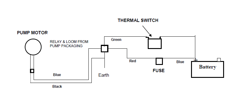
WIRING DIAGRAM 2b: EWP®WITH THERMAL SWITCH - PART # 0402

OPTION 3: CONTINUOUS RUNNING (Recommended for race vehicles, very hot climate and cars running on LPG.)
Continuous EWP®150 Alloy Electric Water Pump operation may be required for some road or race engine applications, in some very hot climatic conditions and engines fitted with liquid petroleum/butane gas (LPG) conversion.
This choice will provide maximum flow from your EWP®150 under all operating atmospheric condition without a Digital Controller or a Thermatic Switch fitted. Should you choose this method you lot should retain the engine thermostat and drill i or two holes (suggest 5mm) in the plate to ensure a pocket-size volume of coolant flows through the cooling organization during operation. Depending on the operating temperature required in some engines, the center of the thermostat plate may need to be removed.
WIRING DIAGRAM 3: EWP® CONTINUOUS RUNNING:
BLEEDING THE EWP®
1. Make full the entire engine cooling organisation with appropriate coolant.
2. Practice not kickoff the engine
3. Hardwire the EWP® directly to the vehicle's bombardment or a 12v power source.
four. With the radiator cap off, run the EWP® for short periods to ensure no air is trapped in the cooling arrangement. Meridian up the radiator with coolant ensuring all air is totally eliminated from the unabridged cooling organisation. Re-run the EWP®150 for a short period.
5. Supercede the radiator cap and reconnect the EWP®150 to the wiring system supplied.
RUNNING THE EWP®
Start engine to confirm no leakage at radiator hose and re-torque radiator hose clamps. Monitor the engine temperature, which should take longer than usual to accomplish steady country. If the ignition is left on (or if a turbo timer is connected) afterwards a hot shut down, the pump volition continue to run and finish engine heat soak. Re-tighten the hose clamps subsequently a few hours running at temperature and again afterward 20 hours running. Check for leaks. NB: The heater circuit may have longer than normal to warm upwards.
EWP ® 150 INSTALLATION RECOMMENDATIONS
To ensure maximum life and optimum operation from your new EWP Davies, Craig recommends:
• Storage - If a EWP ® is installed in your vehicle's engine cooling organisation, stored and/or non started or driven for more than 3 months, e.chiliad. a bear witness/static display or race auto, it'due south strongly recommended the EWP® is operated for approximately 5 mins constant running every month. This will minimise the build-up of any sediment in the EWP and too lubricate all parts within the pump.
• Heater - For improved heater performance on vehicles which have the heater inlet (return) and outlet ports in the mechanical pump housing (referred to in "Warnings"), Davies, Craig advise the fitment of the Electric Booster Pump, EBP, office # 9001. This unit fits into the heater hose and boosts coolant flow through the heater excursion and/or cylinder heads. Check out website www.daviescraig.com.au
• LPG (Liquid Petroleum Gas or Butane) vehicles require constant flow through the LPG converter and if the EWP is used in conjunction with the EWP® & Fan Digital Controller, we recommend the installation of an Electric Booster Pump EBP® to overcome the converter torso freezing at start upwardly.
• As a preventative measure, nosotros strongly recommended you lot flush out your engine's cooling organisation every 6 months or 10,000kms to assistance remove any congenital upwards of sediment.
WARNINGS
• Do not operate your EWP® dry as seal impairment may occur and your warranty may be jeopardised.
• Use of the EWP® after removing the pump impeller or deleting the mechanical pump pulley from the belt system may increase maximum engine speed. Running an engine at higher than normal speeds may affect other engine components.
• Engine temperature must be monitored closely at all times more than especially afterwards installation and until your EWP® operational procedures have reached your expectations.
• The EWP® tin handle near rust particles, shale and sludge constitute in cooling systems merely large rust particles should exist flushed from the radiator earlier the EWP® is installed.
• Some engines may require special bleeding procedures to remove all air from their cooling system. The EWP® must exist completely total of coolant at all times to achieve the life expectations of your EWP® and to ensure your warranty is non jeopardised.
• Do not use the vehicle's engine management system or wiring connected to the vehicle's engine management system (ECU) as an ignition source as information technology may crusade failure of the management system and/or the electric organisation. The ignition source for your EWP®150 Electrical Water Pump and EWP® & Fan Digital Controller Combo Kit must be a steady positive supply of 12-14V DC.
• Vehicles with both heater circuit inlet (return) and outlet ports in the mechanical pump housing volition endure reduced heater performance unless the heater returns position is relocated.
• The engine cooling arrangement must utilize coolant as specified by the vehicle'south manufacturer.
• The EWP® is a 'circulation' pump ideal for well-nigh 'closed circuit' pressurised automotive cooling systems.
• The EWP® is non a 'self-priming' water pump and therefore will not produce its full catamenia without a positive 'caput' in an 'open' system.
• The EWP® impeller tip clearance has been designed to achieve maximum efficiency and is therefore very close to the housing. When new and bedding in, the impellor may touch the internal wall of the EWP® housing causing a slight noise. This sound volition cease within a very brusque time.
Plumbing fixtures OPTION:
EWP® HEADER-ADAPTOR KITS ~ Suit Chevrolet Pocket-size & Large Cake engines
To complement the fitment of your EWP®150 Electric Water Pump and EWP® & Fan Digital Controller Combo Kit to your Chev BB or SB engine, a EWP® Header-Adaptor Kit is available to supervene upon the existing mechanical water pump. These simple do-it-yourself kits are supplied with fitting instructions and a 3D video is available for viewing on our website www.daviescraig.com.au
WARRANTY
We warrant that for a period of two years or 2000 hours continuous running (whichever is the lesser) from the engagement of purchase, we shall behave out, free of cost, any repairs that are reasonably necessary to right any fault in the operation of your Electric Water Pump provided that such a fault is directly attributable to a defect in the workmanship or materials used in the manufacture of the part(s) and is non due to installation other than described in these instructions. Labour and consequential costs are excluded. DAVIES, CRAIG PTY. LTD.
All-time Sellers
Word on The Street
I actually like how the website shows the parts highligted on the cars and so y'all know EXACTLY what you are ordering. Prices are correct too!!
FORD, FORD MUSTANG, MUSTANG GT, SVT COBRA, MACH 1 MUSTANG, SHELBY GT 500, COBRA R, BULLITT MUSTANG, SN95, S197, V6 MUSTANG, Play a joke on Trunk MUSTANG, AND 5.0 MUSTANG ARE REGISTERED TRADEMARKS OF FORD MOTOR Company. Contrivance, DODGE CHALLENGER, DAYTONA 392, DAYTONA R/T, Dodge CHARGER, SRT 392, SRT8, R/T, RALLYE REDLINE, SCAT PACK, SRT HELLCAT, SRT DEMON, T/A, PENTASTAR, AND HEMI ARE REGISTERED TRADEMARKS OF FIAT CHRYSLER AUTOMOBILES (FCA). SALEEN IS A REGISTERED TRADEMARK OF SALEEN INCORPORATED. ROUSH IS A REGISTERED TRADEMARK OF ROUSH ENTERPRISES, INC. CHEVROLET, CHEVROLET CAMARO, CAMARO, LS, LT, LT1, SS, Z/28, ZL1, AND ECOTEC ARE REGISTERED TRADEMARKS OF Full general MOTORS LLC.. AMERICANMUSCLE HAS NO Affiliation WITH THE FORD MOTOR COMPANY, ROUSH ENTERPRISES, FIAT CHRYSLER AUTOMOBILES, SALEEN, OR General MOTORS LLC.. THROUGHOUT OUR WEBSITE AND PRODUCT Catalog THESE TERMS ARE USED FOR IDENTIFICATION PURPOSES Simply. 2003-2021 AMERICANMUSCLE.COM. ®ALL RIGHTS RESERVED

Source: https://www.americanmuscle.com/davies-craig-electric-water-pump-150lph-1117gt-manu-install.html
Posted by: purvistwoulair.blogspot.com
0 Response to "How To Install Electric Water Pump"
Post a Comment